Monday, February 24, 2014

Ali Rahim + Perez-Gomez, ALberto, Pelletier


This week’s reading directly coincides with what I am teaching in my Arch 170 class.  We are covering the topic of representation and re-presentation.  We assigned the students to thoroughly document an object of choice with plans, sections, and elevations.  It was encouraged for students to draw/ photograph/ etc. as many views necessary to recreate the object.  I immediately was asked if using BIM was allowed for this project, (which it is not).   It was fascinating to see how many students, not majoring in architecture, were familiar with 3d computer modeling.   Discouraged when I relayed the news that computers were off limits for this projects, I had a few students argue that it would create the best representation of their chosen object.  (the objective of this assignment is to familiarize student with plan, section, and elevation drawings)  This made me wonder if this traditional method of representation is becoming obsolete? The example of Durand’s Precis des Lecons d’Architectura is presented in “Architectural Representation and the Perspective Hinge”.   It is juxtaposed with two computer generated images form students of Cornell.   Just as the concept of the Master Mason (which we also covered in 170 this week) has become superseded, is there potential for the traditional plan, section, and elevation to be as well? 


The article “Contemporary Techniques in Architecture” also coincidentally corresponded with my studio assignment this week.  We were to fragment a precedent city into components such as water, block type, street corridor, etc 
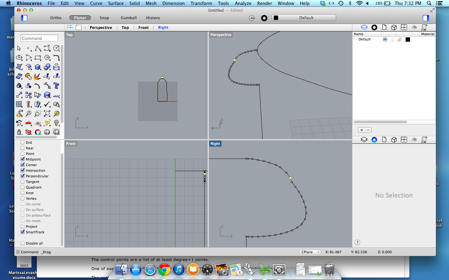
and catalog them.  The first image in Rahim’s article literally cataloged a modeled object and broke it down into its pieces.   I found this helpful at a larger scale of a city to further analyze its parts but also at a smaller scale in modeling our chosen objects in 670.  By breaking down the object into different surfaces, it became clearly how the object was created and assembled.  It also created distinctive surfaces to choose from for the matrical analysis. 


An interesting comparison to our matrical analysis is the idea of ‘lineage or heritage’ mentioned by Rahim.  Our morphed surfaced appear to evolve and change down a lineage line, altering slightly or drastically from one iteration to the next.  The matrical analysis could be read a sort of family tree, with the family changing with time. 


Sunday, February 23, 2014

Proj1b_Images Martrical Analysis


I chose to manipulate the lines in the back surface of the camera. The perspective below shows the modeling space in which in line describes a different distortion.   I chose to start always with the original surface (on left) to show different manipulations from a similar starting point.  By rebuilder the surface and adding more control points, I manually dragged the points to skew the surface in plan, perspective, and elevation.  I started by selecting multiple points, then in my efforts for more flexibility in shape, began to drag singular control points.  


A closer view at a select row of manipulations. 


In the elevations below, the pieces on the far right are the original surfaces; they become more intricately distorted as they move to the left.  To better articulate my exploration of manipulations in various directions, I provided wire frame and shaded views for the surfaces.   


I find the plans helpful because they describe how the surface was pushed and pulled from the front and back.  It was  easiest to manipulate the points and lines from this view.  I find these images to be more evocative than the elevations as they show more movement in the lines and surfaces.  Some of the elevations appear deceiving as they do not show as much divergence as the plans.    


Saturday, February 22, 2014

Revisions to Project 1a


For my revision of Project 1a, I chose to focus on following critiques in the interest of time:

1. Splitting the lens
2. Remodeling the top of the camera
3. Creating more rounded edges on the side and back of the handle
4. Connecting the surfaces seamlessly
5. Eliminating straight edges where curved geometry was needed
6. Adding more sections/plans for lofting


I tried the Fillet command to smooth between surfaces.  Sometimes it did not fully extend the length of both surface though, any ideas why?


Splitting the lens

Creating sections  for the curved top of the camera.  I then lofted these together as opposed to utilizing the Drape tool int he previous iteration.  


For the rear portion of the camera, I modeled the sections of the edge and rotated them to create a curved edge, followed by a Loft.


  I do like how the rounded edged turned out with the lofting of the rotated sections, looks significantly more realistic.  In the rendered view, I still see some disconnects between edges.  Where I created a surface to mitigate the gap between the top loft and the side, it looks like a hard edge.  Is there some kind of Smooth tool?  Similar to what Lori was using in 3D Max?

For project 1b, I will focus on the back piece I show above.


Thursday, February 13, 2014

More Progress on Camera


The above section shows where I am terminating the model.  


I outlined the back on the camera to model the curve in section. 


I then used this outline and lofted two sections of the back together.  


I created a surface out of curved planes to cap the edge of the camera.


I began to model the front curve of the lens.  I now need to figure out a way to tim the rest of the beginning of the lens.  I attempted the 'trim' tool but it will not allow to me to cut a lofted plane.  Any suggestions?  


Monday, February 10, 2014

Camera


Camera Handle Model


I started the model in plan and edited the controls points in the curve to match the outline of the camera


Next, moving to section to model the lip underneath the capturing button.  Here I needed to rebuild and add more control points to edit and match the lip.  


By copying and pasting the plan vertically, I was able to use these as rails for sweep tool.


I attempted to draw the back on the camera in section and loft them together.  


For the top, I used the drape tool and edited the control points to develop the slope of camera. 

Some issues I'm having: 
how to seamlessly join the drape with the sides of the model.  

Sunday, February 9, 2014

Morphosis


Death Cube"K"
The Neoformations of Morphosis


Morphosis: the sequence or manner of development or change in an organism or any of its parts. The firm's unique building designs are made possible through parametric modeling. In the article, the idea of "Mutation is progress and Progress is mutation" is discussed. I find Morphosis' buildings to exemplify this concept at they mutate or warp their designs, it progresses to a new style. Peter Cooper described Morphosis' design for the Cooper Union building to be “as free as water and air." However, criticisms of this building lend that it is does not engage with its site; it does not respond to the context. "Scapelands," discussed in "The Neoformations of Morphosis," brings up the point of displacement and shifting of location.


http://www.archdaily.com/40471/the-cooper-union-for-the-advancement-of-science-and-art-morphosis-architects/


University of Cincinnati by Morphosis 


Morphosis style rejects the "postmodern" with its fragmented designs. Mentioned in this article is Metropolis. The stage sets and designs for Metropolis remind me of the sharp edges of the Cooper Union building. The sets are artistically jagged and skewed from the correct perspective. One can argue that the Morphosis attempted to warp reality with their designs. For example, the "angled
walls frame the interconnecting spaces of the Friedland Jacobs Communications offices and the Ove Arup and Partners Corporate Offices, giving rise to perspectival distortions that "worn" in from one zone to another." The parallel between the two would make for an interesting debate.