Monday, March 3, 2014

1b + 1c


Research question: Now having in mind the objective for project 1c, I am asking at what point will a surface become "unmodelable" ie. cannot be made a solid object.  


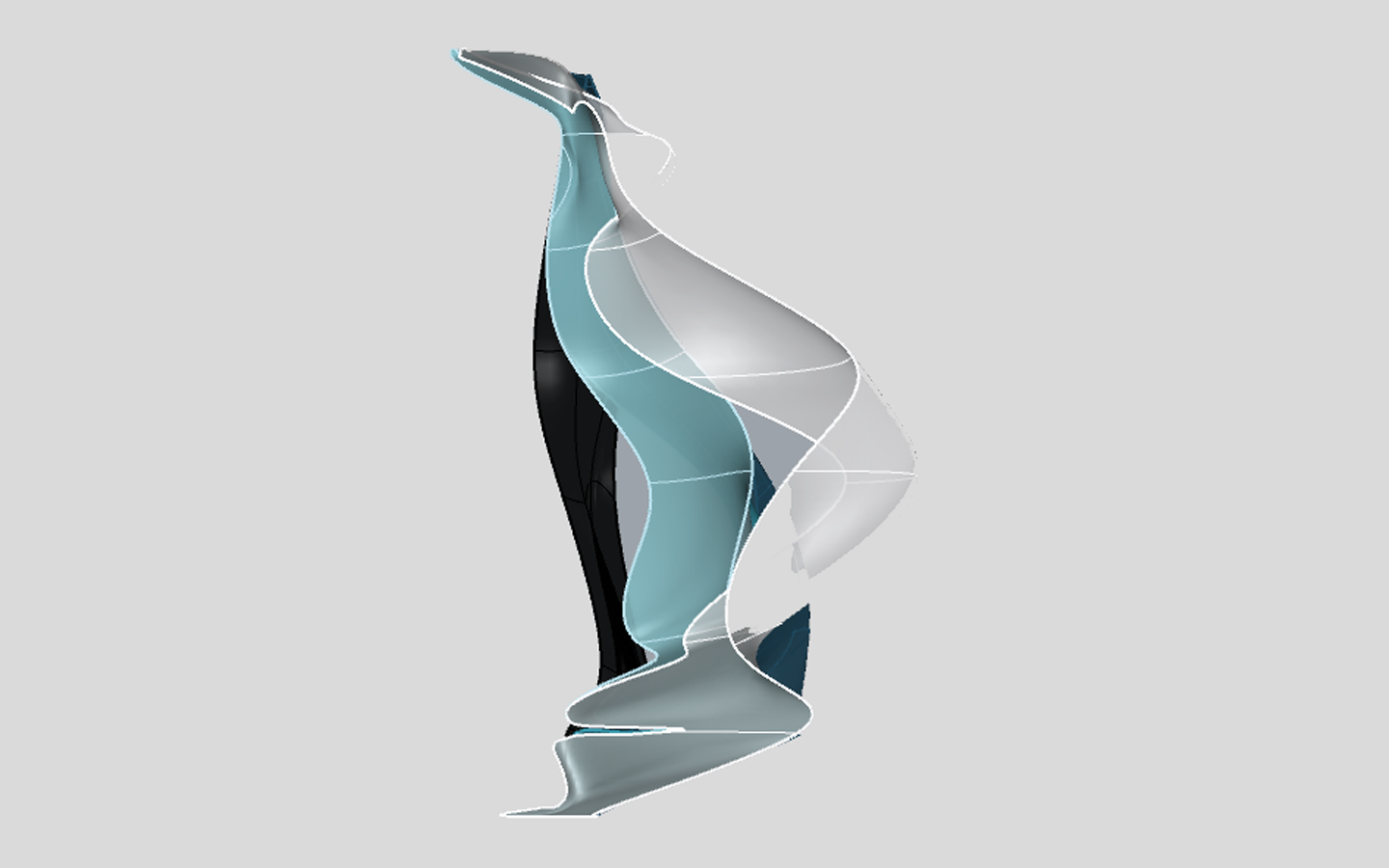
I began by reexamining my chosen surface for 1b matrical analysis.  By splitting the original object, I was able to focus on a sliver of the curve rather than the entire plane.  


This view shows a portion of the martical analysis revisited.  


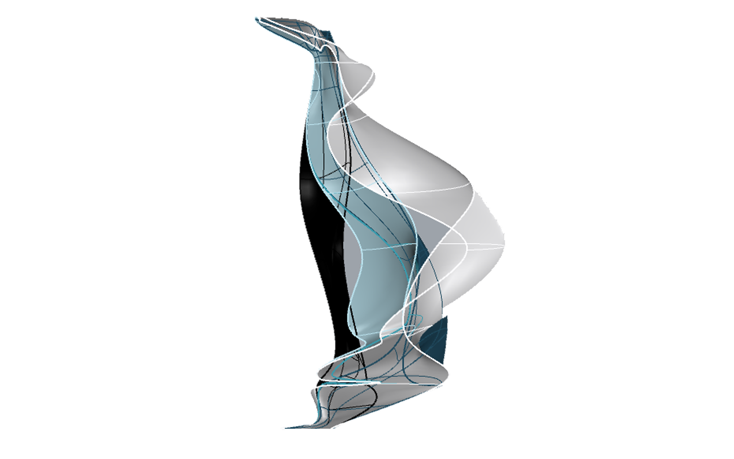
I then alined the deformed objects behind one another to see the change in each piece at once. 
Then following images are of different rows and manipulations.   


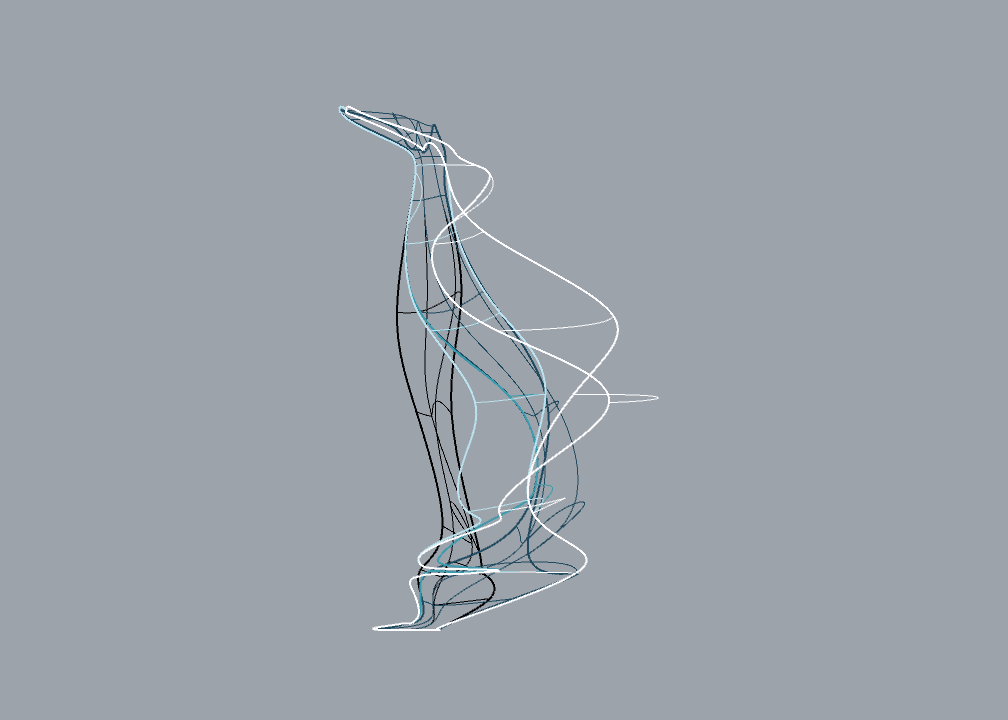
As some of these curved become more complex, I am careful to chose which ones I will make solids to 3D print.  The answer to the research question: When a surface begins to fold over itself, it becomes very difficult to create a solid figure.    


 Finally, I chose a few surface pieces to create printable solids.  I began by copying and pasting the cruves and creating surface out on the voids between them.  I found it easier to loft the edges of the curves.   I also tired extruding surface curves.  Below are the surface pieces I hope to print.


Sunday, March 2, 2014

Versioning and Inchoate


SHoP’s Versioning solidified a few concepts I was questioning for the matrical analysis.   The discussion of versioning begins with a traditional idea of how the term implies replicating an original that can be traced and measured through evolution of one specific source.  In this case, versioning relies on a design agenda and is centered on detailed actions.    The example of the highway system better explains this thought.   It is explained that there is no one basis highway; rather there are various components of highways that are sued to construct a road better for its context.  It is not relied on one prototype, which is unimportant to versioning. 


Side note:I found it fascinating that Brunelleschi used a method of versioning for his Duomo.  Based on the loading pattern, there is not one master brick for the project,   


representation :modelling :: modelling : versioning

This linear expression is in essence our projects for the first half of the semester. 


I really enjoyed reading about the take on versioning in terms of the ‘façade’. The way we see facades has dramatically changed over centuries.  Today we see facades as skins of building.  This stems from not only aesthetic implications, but also structural.  The model of the load bearing Renaissance façade is compared to the invention of the steel frame in which the plan does not have to correlate with the elevation.  This allowed for more design freedom.  Lastlty, the readers are presented with Dieste’s skins and the abstractions behind the geometry. 


Dieste's church in Uruguay 


In Angelil’s Inchoate, we see a method of versioning explained and analyzed in the case of architectural education.   With technology ever changing, the teaching behind this field must adapt quickly.  I find it difficult to work with professors who are resistant to the changing world, whether in concept, theory, technology, etc.


Monday, February 24, 2014

Ali Rahim + Perez-Gomez, ALberto, Pelletier


This week’s reading directly coincides with what I am teaching in my Arch 170 class.  We are covering the topic of representation and re-presentation.  We assigned the students to thoroughly document an object of choice with plans, sections, and elevations.  It was encouraged for students to draw/ photograph/ etc. as many views necessary to recreate the object.  I immediately was asked if using BIM was allowed for this project, (which it is not).   It was fascinating to see how many students, not majoring in architecture, were familiar with 3d computer modeling.   Discouraged when I relayed the news that computers were off limits for this projects, I had a few students argue that it would create the best representation of their chosen object.  (the objective of this assignment is to familiarize student with plan, section, and elevation drawings)  This made me wonder if this traditional method of representation is becoming obsolete? The example of Durand’s Precis des Lecons d’Architectura is presented in “Architectural Representation and the Perspective Hinge”.   It is juxtaposed with two computer generated images form students of Cornell.   Just as the concept of the Master Mason (which we also covered in 170 this week) has become superseded, is there potential for the traditional plan, section, and elevation to be as well? 


The article “Contemporary Techniques in Architecture” also coincidentally corresponded with my studio assignment this week.  We were to fragment a precedent city into components such as water, block type, street corridor, etc and catalog them.  The first image in Rahim’s article literally cataloged a modeled object and broke it down into its pieces.   I found this helpful at a larger scale of a city to further analyze its parts but also at a smaller scale in modeling our chosen objects in 670.  By breaking down the object into different surfaces, it became clearly how the object was created and assembled.  It also created distinctive surfaces to choose from for the matrical analysis. 


An interesting comparison to our matrical analysis is the idea of ‘lineage or heritage’ mentioned by Rahim.  Our morphed surfaced appear to evolve and change down a lineage line, altering slightly or drastically from one iteration to the next.  The matrical analysis could be read a sort of family tree, with the family changing with time. 


Sunday, February 23, 2014

Proj1b_Images Martrical Analysis


I chose to manipulate the lines in the back surface of the camera. The perspective below shows the modeling space in which in line describes a different distortion.   I chose to start always with the original surface (on left) to show different manipulations from a similar starting point.  By rebuilder the surface and adding more control points, I manually dragged the points to skew the surface in plan, perspective, and elevation.  I started by selecting multiple points, then in my efforts for more flexibility in shape, began to drag singular control points.  


A closer view at a select row of manipulations. 


In the elevations below, the pieces on the far right are the original surfaces; they become more intricately distorted as they move to the left.  To better articulate my exploration of manipulations in various directions, I provided wire frame and shaded views for the surfaces.   


I find the plans helpful because they describe how the surface was pushed and pulled from the front and back.  It was  easiest to manipulate the points and lines from this view.  I find these images to be more evocative than the elevations as they show more movement in the lines and surfaces.  Some of the elevations appear deceiving as they do not show as much divergence as the plans.    


Saturday, February 22, 2014

Revisions to Project 1a


For my revision of Project 1a, I chose to focus on following critiques in the interest of time:

1. Splitting the lens
2. Remodeling the top of the camera
3. Creating more rounded edges on the side and back of the handle
4. Connecting the surfaces seamlessly
5. Eliminating straight edges where curved geometry was needed
6. Adding more sections/plans for lofting


I tried the Fillet command to smooth between surfaces.  Sometimes it did not fully extend the length of both surface though, any ideas why?


Splitting the lens

Creating sections  for the curved top of the camera.  I then lofted these together as opposed to utilizing the Drape tool int he previous iteration.  


For the rear portion of the camera, I modeled the sections of the edge and rotated them to create a curved edge, followed by a Loft.


  I do like how the rounded edged turned out with the lofting of the rotated sections, looks significantly more realistic.  In the rendered view, I still see some disconnects between edges.  Where I created a surface to mitigate the gap between the top loft and the side, it looks like a hard edge.  Is there some kind of Smooth tool?  Similar to what Lori was using in 3D Max?

For project 1b, I will focus on the back piece I show above.


Thursday, February 13, 2014

More Progress on Camera


The above section shows where I am terminating the model.  


I outlined the back on the camera to model the curve in section. 


I then used this outline and lofted two sections of the back together.  


I created a surface out of curved planes to cap the edge of the camera.


I began to model the front curve of the lens.  I now need to figure out a way to tim the rest of the beginning of the lens.  I attempted the 'trim' tool but it will not allow to me to cut a lofted plane.  Any suggestions?